Budding · Taking shape, still changing
Controlling a Dimplex VFMi storage heater without its original controller
Second-hand Dimplex VFMi storage heaters sell for a fraction of the price of new ones. The catch: the matching charge controller (for example the ZWM 05 AC) costs about 2,000 PLN today, roughly the price of three heaters. I wanted to use them to soak up surplus solar power in spring and autumn – I had already tried the idea with an oil-filled radiator and the automation worked – so I had to work out what the heater expects on its control terminals.
Two independent circuits
Once I had bought two heaters and looked inside, it turned out they are built almost identically. They differ in the length of the heating elements and the size of the storage core, which sets the charging power and the heat capacity. The key finding: charging and discharging are completely independent of each other.
- Charging simply means powering the heating elements through a contactor. The power cannot be adjusted smoothly – the elements are either on or off – so the only thing you control is how long they run.
- Discharging means switching on the fan (terminals LE). A plain contact is enough, for example an RT200 bimetallic room thermostat. A curiosity: the RT200 has an extra input from a night-tariff controller that lowers its setpoint by 4 °C.
The full wiring diagram with the terminals (A1/Z1, A2/Z2, LE) is in the VFMi manual (PDF, in Polish).
How the heater limits its own charge
The charge level is governed by a thermostat with a thermocouple inside the storage chamber, under one of the bricks. The knob sets how hot the core is allowed to get.
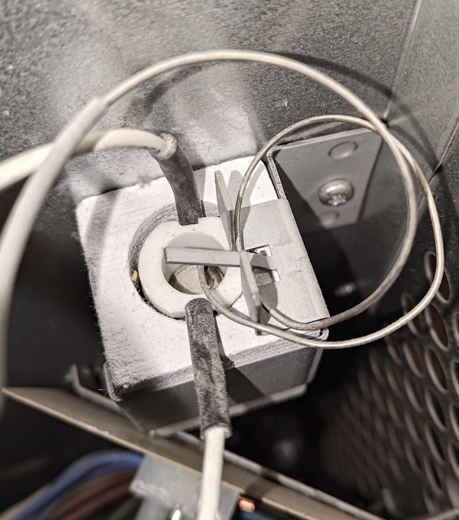
The more interesting part is a second thermocouple hidden in the same component. Terminals A1/Z1 and A2/Z2 lead to it: they power a small cylindrical heater (most likely a resistor) that warms it up. When an external controller applies voltage, the thermocouple “sees” a higher temperature and disconnects the elements earlier. So the charge controller does not measure anything in the heater – it simply fools its thermostat.
The ED signal
The ED signal is 230 V AC switched on and off in a 10-second cycle; what matters is for what share of the cycle it is applied. The logic is inverted – the longer the voltage is on, the less the heater charges. The relationship from the ZWM 05 AC manual:
| Requested charge | ED signal (on-time in a 10 s cycle) |
|---|---|
| 0% | above 80% – charging blocked |
| 10% | 72% |
| 20% | 64% |
| 30% | 57% |
| 40% | 49% |
| 50% | 41% |
| 60% | 33% |
| 70% | 25% |
| 80% | 18% |
| 90% | 10% |
| 100% | 2% |
For example, to charge the core to about half, apply full voltage for about 4 s, then nothing for 6 s, and repeat.
In practice: leave A1/Z1 and A2/Z2 unconnected, turn the knob to maximum, and the heater charges fully. When charging from solar surplus that is exactly what I want – store as much as the sun provided – so I do not need a charge controller at all.
What this means for automation
- Charging: a contactor on the heating-element supply, switched by the automation.
- Discharging: a contact on the fan terminals – a thermostat or a relay driven by Home Assistant.
- Optionally: capping the charge with the ED signal, if the heater were to charge on a night tariff instead of solar.
A warning: these heaters run on three-phase 400 V, so connecting them is a job for a qualified electrician.
These are my conclusions from taking the heaters apart and reading the manuals, not service knowledge. If something does not add up, I will gladly correct it.
Source: my thread on elektroda.pl (in Polish) – Jak sterować Dimplex VFMi bez oryginalnego sterownika: sygnały na wejściach sterujących (July–September 2026).